Dimension index · nine catalogued sizes
Boot size chart, and how to read one
Nine harness sizes across three charts, every bore printed twice: GHSB-714 passes over 32.00mm and closes to 14.00mm.
Every diameter on a boot chart is two numbers
Nine harness boot sizes are catalogued in the sheets this site works from: three GHSB straight, two GHRB right angle, three GHS2-N two-outlet and one GHS3-N three-outlet. All three charts are below, unedited.
Each diameter is quoted twice. The letter a is the bore as supplied and it is a floor, so nothing wider will pass over. The letter b is the bore after unrestricted recovery and it is a ceiling, so nothing narrower will be gripped. No sheet in the pack states either of those things in words.
GHSB-714 reads 32.00 then 14.00 at H, and 32.00 then 7.00 at J. A 28.0mm connector shell sits inside the H span: under the 32.00 that lets it on, over the 14.00 where the wide end runs out of shrink. A 9.5mm cable behind it clears the narrow end's 7.00 by 2.5mm.
With a 6.0mm cable behind that same connector the size fails, though nothing about the connector changed. The narrow end reaches 7.00mm and stops there. It looks fitted. Nothing is sealed.
The test runs at both ends, on both figures. A single "size" is not something these charts publish.
What each part of a boot chart is saying
- a (min)
- The bore as supplied, before heat. A minimum, so it is the largest diameter the part will pass over.
- b (max)
- The bore after unrestricted recovery, with nothing inside the moulding. A maximum, so it is the smallest diameter the part will still close onto.
- ±10% columns
- P, R, U and JO on the straight and right angle charts; L1, L2 and L3 on the outlet charts. Mostly lengths.
- ±20% columns
- HW, JW, X and Y on the straight and right angle charts; T1 and T2, T3 on the outlet charts. Walls, where the band is widest.
- No percentage at all
- H, J, D1 and D2, 3 carry no tolerance figure. They are an absolute minimum and an absolute maximum, and the a-to-b pair already does that job.
- A dash in a cell
- No figure is published for that size in that column. Not a zero, and not permission to interpolate from the row above.
- s and f
- The other convention in the same catalogue. The bushing boot charts label their columns s and f, and print the legend the harness charts never do. D and d are internal diameters, s is as supplied, f is after free recovery.
- Free recovery
- Shrinkage with nothing inside the moulding to stop it. Every b figure is a free-recovery figure, which is why a fitted boot never measures one. Glossed with the other trade words.
Straight boots — GHSB, three sizes
| Product code | H a (min) | H b (max) | J a (min) | J b (max) | P b (±10%) | R b (±10%) | U b (±10%) | JO b (±10%) | HW b (±20%) | JW b (±20%) | X b (±20%) | Y b (±20%) |
|---|---|---|---|---|---|---|---|---|---|---|---|---|
| GHSB-111 | 25.60 | 10.30 | 23.80 | 4.70 | 38.00 | 21.20 | 10.00 | 8.30 | 2.00 | 1.20 | 18.00 | 13.00 |
| GHSB-714 | 32.00 | 14.00 | 32.00 | 7.00 | 65.00 | 36.00 | - | 17.00 | 1.80 | 1.80 | - | - |
| GHSB 202-4 | 37.00 | 20.00 | 37.00 | 8.40 | 76.00 | 46.00 | - | 14.50 | 1.70 | 1.30 | - | - |
All dimensions in mm, as printed on the manufacturer's Straight Type sheet.
Right angle boots — GHRB, two sizes
| Product code | H a (min) | H b (max) | J a (min) | J b (max) | P b (±10%) | R b (±10%) | JO b (±10%) | HW b (±20%) | JW b (±20%) | X b (±20%) | Y b (±20%) |
|---|---|---|---|---|---|---|---|---|---|---|---|
| GHRB-111 | 25.70 | 10.50 | 22.00 | 4.80 | 24.50 | 25.00 | 8.10 | 2.00 | 1.00 | 16.00 | 14.00 |
| GHRB-151 | 43.00 | 26.00 | 41.00 | 10.00 | 52.00 | 44.00 | 17.50 | 3.00 | 1.00 | 25.00 | 25.00 |
All dimensions in mm, from the manufacturer's Right Angle Type sheet. No U column exists on this chart. The lipped edition of it prints J on GHRB-151 as 40.00 rather than 41.00. Both readings, and the three further cells that differ on the straight pair, are set out on right angle and straight boots.
Outlet boots — GHS2-N and GHS3-N, four sizes
| Product code | D1 a (min) | D1 b (max) | D2, 3 a (min) | D2, 3 b (max) | L1 ±10% | L2 ±10% | L3 ±10% | T1 ±20% | T2, T3 ±20% |
|---|---|---|---|---|---|---|---|---|---|
| GHS2-N-306 | 13.5 | 6 | 6.6 | 3.3 | 24 | 15.5 | 25 | 2 | 1.5 |
| GHS2-N-612 | 27 | 12.4 | 13.2 | 6.1 | 53.3 | 33 | 55 | 2.5 | 2 |
| GHS2-N-1218 | 39 | 18 | 27 | 12.4 | 79 | 56 | 80 | 3 | 2.5 |
| GHS3-N-407 | 14 | 6.6 | 6.6 | 3.6 | 46 | 31 | 15.7 | 2 | 1.5 |
All dimensions in mm. GHS2-N rows from the manufacturer's 2-Way Boot sheet, Issue 1, September 2024. The GHS3-N-407 row comes from the 3-Way Boot sheet of the same issue, which uses one identical column set, so all four rows index against each other directly.
Which columns carry ±10%, and which carry ±20%
The bands are not applied evenly. L1, L2 and L3 run at ±10% while T1 and T2, T3 run at ±20%. On the straight and right angle charts it is P, R, U and JO at ±10%, and HW, JW, X and Y at ±20%.
A ±10% band on a long dimension is wide in absolute terms. GHSB 202-4 publishes P at 76.00mm, permitting 68.40mm to 83.60mm. That is over 15mm for a clearance behind a backshell to absorb.
The ±20% band is the one that catches a drawing out. GHS3-N-407 publishes T1 at 2mm, so a 1.6mm wall and a 2.4mm wall are both in specification. Where 2mm was modelled into a 2mm gap, half of that band is an interference, and every part in that half is correct.
The reverse trap is the a and b columns. No ± sign reads as loose. They are the two hard limits on the chart.
The letters are dimensioned, never defined
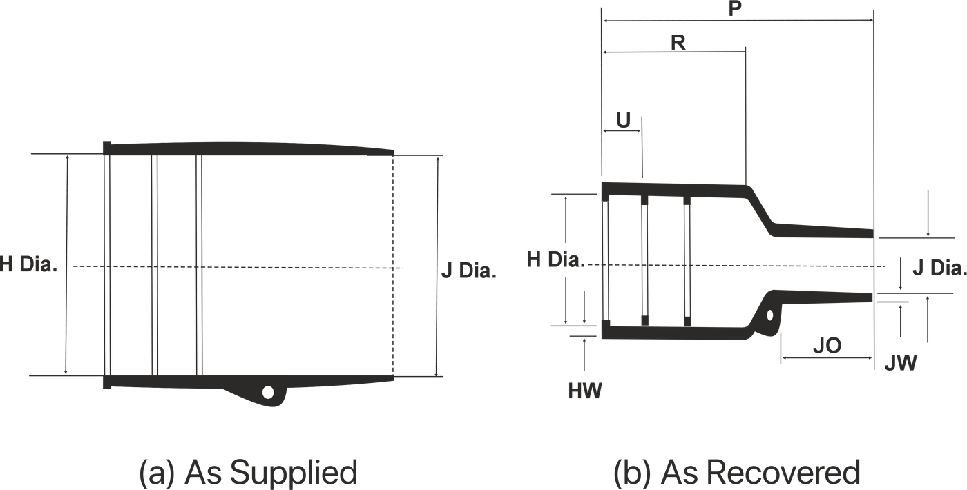
H, J, P, R, U, JO, HW, JW, X and Y appear across these charts with no written legend anywhere in the sheets. Each is an arrow on the dimensioned drawing printed beside its own selection chart, and that drawing is the only definition published. None is reconstructed here from the numbers: a letter guessed wrong survives into a drawing and then into an order.
What the drawing gives you, and what it does not
The profile is drawn twice on each sheet, as supplied and as recovered. That pair of outlines is the clearest published statement of what a and b are.
Reading a letter's position off it is safe. H and J are arrowed at the two open ends, P and R run along the profile, HW and JW sit on the walls.
Reading an absence off it is not. A callout can be drawn on the profile and still be blank in the chart for a size. U is drawn on the straight boot and left blank against GHSB-714 and GHSB 202-4 above. The drawing carries the geometry; only the chart says which sizes have a figure for it.
Recording a boot you are replacing
This recording method is this site's, not the manufacturer's. Six figures, taken in this order, make an unmarked part comparable with a published row.
A photograph, before anything is cut
The exit angle, the end sitting on the connector and the end on the cable. All three are gone once the boot is off, and all three narrow the search faster than a dimension does.
The old boot's diameters, labelled b
Anything measured on a boot already shrunk is a recovered figure, readable only against a b column. Written into an enquiry as a plain size, it gets matched against the wrong end of the chart.
Why that figure is not even a clean b
A fitted boot never recovered freely. It stopped where the connector stopped it. The number sits between that size's a and its b and equals neither, so it bounds the search rather than settling it.
The two diameters the chart is indexed by
The outside diameter of the shell the wide end covers, and the outside diameter of the cable behind it. Both taken on the hardware, not on the old moulding.
Length behind the shell, and the clearance
P and R are ±10% columns, so a published 52.00mm can arrive at 57.20mm. The clearance decides whether that matters.
The wall, read against ±20%
T1, HW and JW are ±20% columns. A 2mm wall is a 1.6mm to 2.4mm wall. Where the gap is tight, that band belongs in the enquiry rather than in an assumption.
Three things these charts do not cover
GRB and GSB are absent by design. They are bushing boots for a cable termination box, four sizes in each profile, shrinking at 125°C against 120°C. Their columns are labelled s and f, and their letters are their own. Both charts are on insulating boots at busbar and bus-duct terminations.
GHYB, the Y type, is dimensioned on its own drawing against H, J, K, P, R & S and W, and one size is catalogued. It sits with the parts sorted by outlet, on boots by outlet count.
Breakouts are indexed by core count instead, and run to far more rows. The breakout size chart is separate for that reason, and which family a job needs is settled on breakout or boot.
A size question answers in one reply when it carries a pair
Two diameters, each measured on the hardware and each written as its own number, either land on a catalogued row or rule every row out. One figure off an old boot does neither.