Insulcore-NT · GAB series
Anti-tracking cable breakouts
Three legs, nine catalogued sizes: the smallest takes 60 mm down to 20 mm, the largest 200 mm down to 60 mm.
Three cores, and nothing else
Insulcore-NT is catalogued for 3 core cable only. Nine codes run GAB-0820 to GAB-3060, and the published chart carries no 2, 4, 5, 6 or 7 core size.
It seals the crutch of 3 core PVC and PILC cable rated up to 36 kV. The body is non-tracking cross-linked polyolefin and the inner face is coated with water-resistant mastic.
The sheet names PVC and PILC. It does not name XLPE or rubber sheaths, where the Insulcore-LV chart names all four.
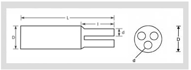
Selection works the same way as it does lower down the range. You match the sheath diameter at the crutch against the D pair, and one core diameter just past it against the d pair.
Insulcore-NT anti-tracking cable breakout, GAB series
A moulded three-leg heat shrink breakout for the crutch of 3 core PVC and PILC cable to 36 kV, in non-tracking cross-linked polyolefin with a water-resistant mastic lining.
- Non-tracking cross-linked polyolefin, internally coated with water-resistant mastic
- Weather and UV resistance
- Resistance to chemical, solvent, corrosion and fungus
- No tracking, erosion or flame failure up to 3.25 kV for 20 minutes, ASTM D2303
| Cores | 3 only |
|---|---|
| Cable types named | PVC and PILC |
| Rated voltage | Up to 36 kV |
| Catalogued sizes | 9 codes, GAB-0820 to GAB-3060 |
| Body internal diameter D | 60 to 200 mm as supplied; 20 to 60 mm after free recovery |
| Leg internal diameter d | 25 to 70 mm as supplied; 8 to 30 mm after free recovery |
| Body material | Non-tracking cross-linked polyolefin |
| Lining | Water-resistant mastic |
| Shrink temperature | 125 °C |
| Continuous temperature limit | −40 to +100 °C (datasheet figure) |
GAB selection chart, all nine sizes
| Code | Cores | D s, min | D f, max | d s, min | d f, max | L s, min | L f, max | l s, min | l f, min | Tb, +10% | Tc, +10% |
|---|---|---|---|---|---|---|---|---|---|---|---|
| GAB-0820 | 3 | 60 | 20 | 25 | 8 | 160 | 188 | 45 | 62 | 3.7 | 2.8 |
| GAB-0820 A | 3 | 70 | 20 | 27 | 8 | 155 | 188 | 40 | 62 | 3.7 | 2.8 |
| GAB-1330 | 3 | 80 | 30 | 39 | 13 | 185 | 215 | 60 | 75 | 3.9 | 3.1 |
| GAB-1330 A | 3 | 100 | 30 | 39 | 13 | 185 | 215 | 60 | 75 | 3.9 | 3.1 |
| GAB-2145 | 3 | 110 | 45 | 55 | 20 | 200 | 230 | 70 | 90 | 4.3 | 3.0 |
| GAB-2145 A | 3 | 125 | 45 | 55 | 21 | 190 | 230 | 65 | 90 | 4.3 | 3.0 |
| GAB-2755 | 3 | 140 | 56 | 68 | 28 | 215 | 250 | 80 | 90 | 4.0 | 3.0 |
| GAB-2755 A | 3 | 180 | 56 | 70 | 29 | 210 | 255 | 80 | 90 | 4.0 | 3.0 |
| GAB-3060 | 3 | 200 | 60 | 70 | 30 | 190 | 225 | 70 | 85 | 4.0 | 3.0 |
All dimensions in mm. D is the internal diameter of the body and d the internal diameter of a leg; s is as supplied and f is after free recovery. Tb and Tc are body and leg wall thickness. The manufacturer's chart prints GAB-2145 without its hyphen on the web page and with it on the datasheet; the row is otherwise identical in both.
What the four letters point at
D and L belong to the body, the part that goes over the sheath. d and l belong to a single leg.
Each of the four is published twice. The s figure is what you receive and is a minimum; the f figure is what the part reaches with nothing inside it and is a maximum.
Your cable has to sit between the two. A crutch at 55 mm is inside GAB-0820, which opens at 60 mm and recovers to 20 mm. At 62 mm it is not, and the next code up, GAB-0820 A, opens at 70 mm.
Physical properties
| Property | Value | Method |
|---|---|---|
| Tensile strength | 12 N/mm² (MPa) min. | ASTM D638 |
| Ultimate elongation | 350% min. | ASTM D638 |
| Density | 1.15 ± 0.2 g/cm³ | ASTM D792 |
| Hardness | 45 ± 10 Shore D | ASTM D2240 |
| Water absorption | 0.5% max. | ASTM D570 |
Thermal properties
| Property | Value | Method |
|---|---|---|
| Accelerated ageing | 120 °C for 500 hours | ASTM D2671 |
| Tensile strength after ageing | 11 N/mm² (MPa) min. | ASTM D638 |
| Ultimate elongation after ageing | 300% min. | ASTM D638 |
| Low temperature flexibility, −40 °C for 4 hours | No cracking | ASTM D2671 |
| Heat shock, 250 °C for 30 minutes | No cracking or flowing | ESI 09-11 |
| Shrink temperature | 125 °C | IEC 216 |
| Continuous temperature limit | −40 to +100 °C | IEC 216 |
The two ageing rows report the compound after 500 hours at 120 °C. They are not as-supplied figures, and they are the reason the tensile row appears twice with different values.
Electrical properties
| Property | Value | Method |
|---|---|---|
| Dielectric strength | 15 kV/mm min. | ASTM D149 |
| Volume resistivity | 1 × 10¹⁴ ohm.cm min. | ASTM D257 |
| Dielectric constant | 5 max. | ASTM D150 |
| Resistance to track and erosion | No tracking, erosion or flame failure up to 3.25 kV for 20 minutes | ASTM D2303 |
Values as printed on the manufacturer's anti-tracking breakout datasheet. Two of them are contradicted by the manufacturer's own web page for the same product, which is set out below.
Where the two published sources disagree
Two rows differ between the datasheet and the manufacturer's web page for this product. Dielectric strength is 15 kV/mm minimum on the datasheet and 12 kV/mm minimum on the web page, both to ASTM D149. The continuous temperature limit is −40 to +100 °C on the datasheet and −40 to +110 °C on the web page, both to IEC 216. The tables here follow the datasheet. The gap matters in one direction only: at 12 kV/mm this compound is no stronger a dielectric than the low voltage one, and at 15 kV/mm it is. Neither figure changes the 36 kV rating, which both sources give identically.
What 3.25 kV for 20 minutes proves
One row carries the reason this part exists, and it is the row most often read as a rating.
ASTM D2303 is the inclined-plane test for tracking and erosion of insulating materials. A contaminant flows down the face of a specimen while voltage is applied across it, and the specimen either carbonises or does not.
So 3.25 kV is a bench voltage on a flat sample of compound. It is not a ceiling on the cable, and the same sheet rates the finished part to 36 kV. Two numbers, two different things.
The row proves that the compound went twenty minutes on a wet, contaminated surface without forming a carbon path. It proves nothing about your creepage distance, your pollution level, your crutch geometry or a service life in years.
Read it as a material qualification. It is the evidence that the compound belongs above 3.3 kV at all, and it is not a design figure you can size anything against.
GAB against the low voltage part at the five shared sizes
Five GAB codes have a direct Insulcore-LV counterpart. Every body diameter matches to the millimetre, as supplied and after recovery. What moves is the wall.
| Body D, s → f | Non-tracking | Insulcore-LV | Difference on paper |
|---|---|---|---|
| 60 → 20 mm | GAB-0820, Tb 3.7 / Tc 2.8 | LV3GBB-0820, Tb 3.3 / Tc 2.7 | Body wall 0.4 mm thicker; recovered body length 188 against 184 |
| 80 → 30 mm | GAB-1330, Tb 3.9 / Tc 3.1 | LV3GBB-1330, Tb 3.6 / Tc 3.3 | Body wall thicker, leg wall thinner; leg bore 39 against 36 as supplied |
| 110 → 45 mm | GAB-2145, Tb 4.3 / Tc 3.0 | LV3GBB-2145, Tb 3.5 / Tc 2.9 | Body wall 0.8 mm thicker, the widest gap in the set |
| 140 → 56 mm | GAB-2755, Tb 4.0 / Tc 3.0 | LV3GBB-2755, Tb 3.5 / Tc 3.5 | Body wall thicker, leg wall 0.5 mm thinner |
| 200 → 60 mm | GAB-3060, Tb 4.0 / Tc 3.0 | LV3GBB-3060, Tb 4.0 / Tc 3.0 | Every dimension equal except recovered body length, 225 against 250 |
Why the wrong one goes in
The two parts cannot be told apart by measuring them. At all five shared sizes the body and leg bores are the same figures on both charts.
Two rows in the property tables differ, and neither settles it in the field. Density is 1.15 ± 0.2 g/cm³ against 1.05 ± 0.2 g/cm³, both to ASTM D792, and those tolerance bands overlap across most of their width. Water absorption is 0.5% maximum against 0.2% maximum, to ASTM D570.
The difference that matters carries no number at all. Tracking is a surface process: a carbonised path grows across the face of the insulation rather than through its wall, and a thicker wall is a through-wall figure.
The Insulcore-LV electrical table stops at dielectric constant. It has no ASTM D2303 row. So nothing is published about how that compound behaves on a wet, contaminated surface. That is the condition a crutch in a pit spends its life in.
That is the honest boundary between the two families. Below 3.3 kV the low voltage part is the published answer and this one is over-specified. Above it, the low voltage part is outside its rating and the substitution leaves no trace on any dimension you can check afterwards.
Not published on the anti-tracking sheet — ask the manufacturer
Four things are absent. There is no cable diameter range against a code, only the part's own D and d pairs, so the match is yours to make. There is no IP rating. The low voltage sheet claims IP 68 for the installed system and this one claims none. The lining here is mastic rather than hot melt adhesive. There is no withstand or partial discharge test on the finished breakout, only compound tests. And the sheet carries no issue number, revision date or qualification report reference. The low voltage sheet carries Issue 2, March 2025 and Technical Qualification Report No. QR 1012. Where a crutch measures close to a band edge, confirm the code against both figures before ordering.
Ask about a 3 core size
Four figures pick one of nine codes: the sheath diameter at the crutch, one core diameter just past it, the insulation type and the voltage class.