Boots
Heat shrink boots
Eighteen catalogued sizes: a 13.5mm down to b 6mm at the smallest, s 145mm down to f 72mm at the largest, across two families that shrink at different temperatures.
Outlet count first, geometry second
The order is fixed by what has already been decided elsewhere. Outlet count comes first, because the connector or the harness settled it before anyone opened a catalogue. Geometry comes second, because the enclosure settled that. Diameter comes last, and it is the only one of the three a size table can answer.
One outlet is GHSB-111, GHSB-714 and GHSB 202-4 straight, or GHRB-111 and GHRB-151 at ninety degrees. Two outlets is GHS2-N in three sizes. Three outlets is GHS3-N-407, one catalogued size, a 14mm and b 6.6mm on the entry bore.
The Y is its own entry. GHYB-381-1 is catalogued with a full selection chart of its own. It reads a 19.80mm to b 6.60mm on the entry and a 13.20mm to b 6.60mm on each leg, in the manufacturer's Y-type boot datasheet.
A second set of shapes carries almost the same names and none of the same numbers. GRB-1, GRB-2, GRB-2A and GRB-3 at ninety degrees; GSB-1, GSB-2, GSB-2A and GSB-3 straight. Those belong at a bushing, not at a connector.
a and b, drawn side by side
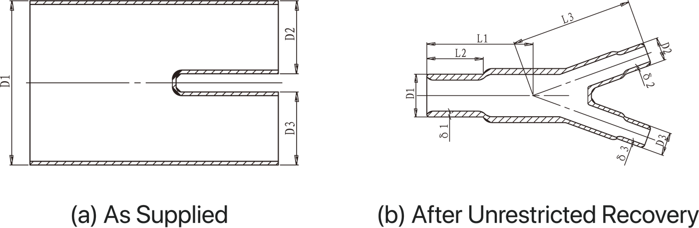
Every catalogued diameter is published as a pair, never as one figure. The manufacturer draws both states and labels them (a) As Supplied and (b) After Unrestricted Recovery.
D1 is the entry bore, D2 and D3 the outlets, L1 to L3 the leg lengths, T the wall. Each diameter carries an a and a b. Each length and wall carries one figure and a tolerance band, ±10% on the lengths and ±20% on the walls.
That is the whole reading method. GHS2-N-612 reads a 27mm and b 12.4mm on D1. It slides over anything up to 27mm and closes down on anything above 12.4mm. A size that satisfies only one end of that window will not seal.
Five places a boot goes
Each page below carries the published dimensions for the parts it names.
One outlet, straight or at ninety degrees
GHSB-111 reads a 25.60mm and b 10.30mm on the entry bore. GHRB-151 reads a 43.00mm and b 26.00mm. Both go on over a connector already mounted to the cable.
Two outlets, three outlets, Y and T
GHS2-N-306, GHS2-N-612 and GHS2-N-1218 for a two-way branch, GHS3-N-407 for a three-way, GHYB-381-1 for the Y. Dielectric strength on this group is ≥20 kV/mm to IEC 60243.
At a busbar or bus-duct termination
GRB and GSB in cross-linked non-tracking polyolefin, internally coated with water-resistant red mastic. 15 kV/mm minimum, and no tracking or erosion failure to 3.25 kV for twenty minutes.
Boots that come off again
Modified silicone rubber, not a shrink material. Bushing diameter 46 to 70mm, maximum system voltage 36 kV for one minute AC, and direct voltage testing without stripping insulation off.
On a harness
Insulation, strain relief and environmental sealing at one point. Oxygen index ≥28% to ISO 4589, flexibility to -55°C to ISO 974.
Two families, almost the same names
Both sets are sold as heat shrink boots. Almost nothing else about them lines up. The GRB and GSB figures come from the manufacturer's right angle and straight boot page.
| GHSB · GHRB · GHYB · GHS2-N · GHS3-N | GRB · GSB | |
|---|---|---|
| Shrink temperature | 120°C | 125°C |
| Goes on to | A connector already mounted to the cable | A bushing inside a cable termination box |
| Material | Cross-linked polyolefin to military specification | Cross-linked non-tracking polyolefin |
| Lining | Supplied with or without adhesive, standard colour black | Water-resistant red mastic, internally coated |
| Dielectric strength | 10 kV/mm min ASTM D149; ≥20 kV/mm IEC 60243 on GHS2-N and GHS3-N | 15 kV/mm minimum |
| Continuous rating | Not published on any of the five sheets | -40°C to +110°C |
| Tracking and erosion | Not published | No failure to 3.25 kV for 20 minutes, ASTM D2303 |
| Fluid and fungus resistance | Good to MIL-I-81765A; no growth to ASTM G-21 | Not published |
| Dimension letters | a as supplied, b after unrestricted recovery | s as supplied, f after free recovery |
| Catalogued sizes | Ten | Eight |
Two tensile figures for the same right-angle boot
The manufacturer's right-angle boot page prints tensile strength 12 N/mm² minimum and ultimate elongation 350% minimum to ASTM D638. The datasheet for the same part prints 9.5 N/mm² minimum and 250% minimum to ASTM D412. After thermal ageing at 175°C for 168 hours it prints 8.5 N/mm² and 200%. Both sources appear here, named. The datasheet is the document a part ships against, so that is the figure worth carrying onto a drawing.
Lining is the fork you cannot take back
Three linings sit under the one word. The harness range is supplied with or without adhesive lining, standard colour black. GRB and GSB are internally coated with water-resistant red mastic. The reusable rubber boot has no lining at all, because it does not seal by bond.
The lining decides what happens the second time. An adhesive or mastic lined boot bonds to what it recovers onto, which makes it a one-way part. The next one goes on to a surface that has to be brought back to clean jacket first.
An unlined boot grips without bonding. That is the property the reusable boot is bought for: it installs and removes as often as required, and the connection can be re-energised immediately after installation.
No continuous temperature rating is published for the harness boots
GRB and GSB publish -40°C to +110°C continuous. The five harness sheets publish a 120°C shrink temperature, a heat shock result, and on GHS2-N and GHS3-N a low-temperature flexibility of -55°C to ISO 974. None publishes an upper continuous limit. Heat shock at 250°C for 30 minutes, and at 200°C for 4 hours to UL 224, are survival tests on a sample rather than a service rating. That figure has to come from the manufacturer against a specific part code.
Where a boot stops
A boot works at an interface. The crutch is not an interface. It is the point inside a multi-core cable where the cores separate, and no boot in either family is catalogued for it.
Past three outlets on a power cable there is nothing here to choose. The low-voltage cable breakout range runs 2, 3, 4, 5, 6 and 7 core, hot-melt-adhesive lined, for PVC, XLPE, rubber and PILC cable up to 3.3 kV. That is the part for a crutch, and outlet count on a boot is not the same quantity as core count on a cable. Where an enquiry uses both words at once, breakout or boot separates them in one line.
Where the numbers are
- Boot size chart, and how to read oneGHSB, GHRB, GHS2-N and GHS3-N in one dimension index.
- Boot, breakout, shroud, sleeve: the wordsCrutch, free recovery, range-taking, lipped, bottle.
- Replacing a boot when the part number is goneA measurement taken off a fitted boot is a b figure.
- MIL-I-81765A, SAE AS81765/1 and the tests on a boot datasheetWhat the military specification actually covers on this product.
- Installing a boot or a breakout120°C and 125°C are material temperatures, not gun settings.
Two numbers name a part code
The largest thing the boot has to pass over, and the smallest thing it has to grip. With an outlet count and an exit angle beside them, the size is settled before anyone is contacted.